Source type A
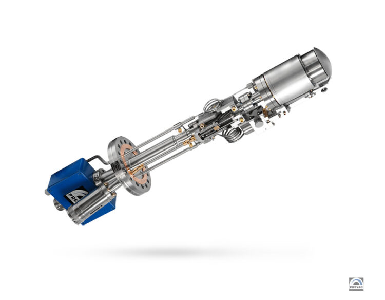
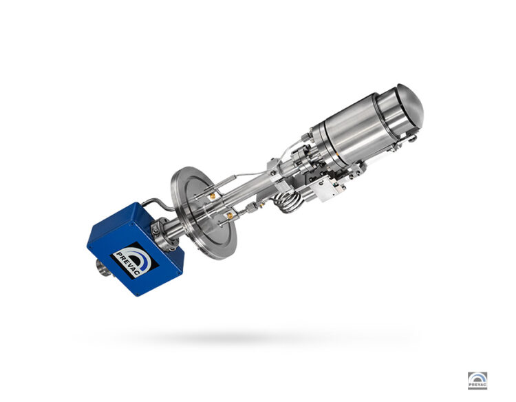
The magnetron source type A is used to apply thin layers with high homogeneity in the sputtering process. The source is compatible with UHV conditions. Thanks to the integrated in-situ tilt system, it can be used in both standard and custom geometry chambers. By using the dome-type design we minimize the space needed to open the shutter.
| Mounting flange |
DN 63 CF, DN 100 ISO-K* |
| Max. power (DC mode) |
400 W DC ** |
| Max. power (RF mode) |
400 W RF ** |
| Max. voltage DC |
1200 V |
| Connector DC/RF |
type 7/16 |
| Target |
|
| form |
circular |
| diameter |
2″ (50.8 mm) ± 0.2 mm |
| thickness |
1 – 6 mm |
| cooling |
indirect |
| Water flow |
min. 1 l/min |
| Max. inlet water temperature |
< 28 °C |
| Max. water pressure |
3 bar |
| Tubing diameter |
Ø6×1 mm PTFE |
| Magnet material |
Neodymium Iron Boride (NdFeB) |
| Magnet max. temperature |
200°C |
| Internal pneumatic shutter |
yes |
| Shutter type |
dome type or flat swing |
| Insitu tilt module |
yes, range +45° ÷ -10° |
| Chimney |
yes |
| Dedicated materials: |
|
|
typical rates [nm/min] for 200 W: |
| Cu |
40,87 nm/min ( distance: 150 mm; target thickness: 3 mm)*** |
| Ti |
10,82 nm/min (distance: 150 mm; target thickness: 3 mm)*** |
| Fe |
15,94 nm/min (distance: 150 mm; target thickness: 1 mm)*** |
| Internal gas inlet |
yes (VCR standard) |
| Working gas |
Ar |
| Max. working pressure |
5×10⁻³ – 1×10⁻¹ mbar |
| Optimal working pressure |
5×10⁻³ – 5×10⁻² mbar |
* Other mounting flanges on request
** The maximum power is determined by the target material
*** Distances depend on the geometry of the chamber and the magnetrons
Source type B
The magnetron source type B is used to apply thin layers with high homogeneity in the sputtering process. The source is compatible with UHV conditions. The source is designed for sputtering magnetic and ferromagnetic materials. It can operate on up to 7 mm thick targets.
| Mounting flange |
DN 63 CF |
| Max. power (DC mode) |
400 W DC ** |
| Max. power (RF mode) |
400 W RF ** |
| Max. voltage DC |
1200 V |
| Connector DC/RF |
type 7/16 |
| Target |
|
| form |
ring |
| diameter |
2″ (50.8 mm) ± 0.2 mm |
| thickness |
1 – 7 mm (magnetic & non-magnetic) |
| cooling |
indirect |
| Water flow |
min. 1 l/min |
| Max. inlet water temperature |
< 28 °C |
| Max. water pressure |
3 bar |
| Tubing diameter |
Ø6×1 mm PTFE |
| Magnet material |
Samarium Cobalt (SmCo) |
| Magnet max. temperature |
350°C |
| Internal pneumatic shutter |
yes |
| Shutter type |
dome type or flat swing |
| Insitu tilt module |
yes, range +45° ÷ -10° |
| Chimney |
yes |
| Dedicated materials: |
|
|
typical rates [nm/min] for 200 W: |
| Cu |
32,84 nm/min ( distance: 160 mm; target thickness: 3 mm)*** |
| Ti |
10,07 nm/min (distance: 160 mm; target thickness: 3 mm)*** |
| Fe |
9,63 nm/min (distance: 160 mm; target thickness: 3 mm)*** |
| Internal gas inlet |
yes (VCR standard) |
| Working gas |
Ar |
| Max. working pressure |
5×10⁻³ – 1×10⁻¹ mbar |
| Optimal working pressure |
5×10⁻³ – 5×10⁻² mbar |
* Other mounting flanges on request
** The maximum power is determined by the target material
*** Distances depend on the geometry of the chamber and the magnetrons
Source type C
The magnetron source type C is both RF‑ and DC‑compatible and can deposit many classes of materials: conductors, semiconductors, and insulators. The source enables the creation of uniform, homogeneous and small-grained thin films; with such advantages as high density (low void area), high specularity (reflectance), and free of radiation damage and broken bonds.
| Mounting flange |
DN 63CF or DN 63ISO‑K for model MS2/63C1,
or DN 100CF or DN 100ISO‑K for model MS2/100C1 |
| Max. power (DC mode) |
400 W DC ** |
| Max. power (RF mode) |
400 W RF ** |
| Max. voltage DC |
1200 V |
| Connector DC/RF |
type 7/16 |
| Target |
Keeper standard |
| form |
circular |
| diameter |
2″ (50.8 mm) ± 0.2 mm |
| thickness |
non-magnetic: 1-6 mm; magnetic: Fe 1mm, Ni 1mm |
| cooling |
indirect |
| Water flow |
min. 1 l/min |
| Max. inlet water temperature |
< 28 °C |
| Max. water pressure |
3 bar |
| Tubing diameter |
Ø6×1 mm PTFE |
| Magnet material |
Neodymium Iron Boride (NdFeB) |
| Magnet max. temperature |
200 °C |
| Internal pneumatic shutter |
yes |
| Shutter type |
dome type or flat swing |
| Insitu tilt module |
yes, range +45° ÷ -10° |
| Chimney |
yes |
| Dedicated materials: |
|
|
typical rates [nm/min] for 200 W: |
| Cu |
34,70 nm/min (distance: 100 mm; target thickness: 3 mm)*** |
| Ti |
6,8 nm/min (distance: 100 mm; target thickness: 3 mm)*** |
| Fe |
32,41 nm/min (distance: 100 mm; target thickness: 1 mm)*** |
| Internal gas inlet |
yes (VCR standard) |
| Working gas |
Ar |
| Max. working pressure |
5×10⁻³ – 1×10⁻¹ mbar |
| Optimal working pressure |
5×10⁻³ – 5×10⁻² mbar |
* Other mounting flanges on request
** The maximum power is determined by the target material
*** Distances depend on the geometry of the chamber and the magnetrons

